Engineered for low reactive power draw, optimized excitation efficiency, and high-performance continuous industrial duty.
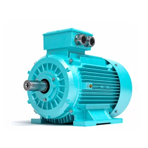
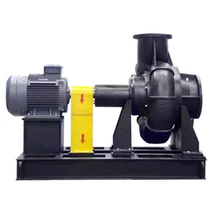
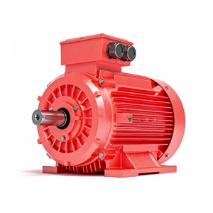
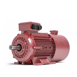
Electromagnetic Fundamentals, Energy Flow, and Mechanical System Balance
In asynchronous machines and three-phase induction electric motors, the no-load current (often represented as \(I_0\)) represents the current drawn by the motor when it is running at rated voltage and frequency but without delivering any mechanical output through its shaft. This current consists of two fundamental components: the magnetizing current (\(I_m\)), which establishes the alternating magnetic flux in the air gap and stator core, and the active power loss component (\(I_{fe}\)), which accounts for the iron losses (hysteresis and eddy currents) and mechanical friction and windage.
Unlike resistive loads where current and voltage are perfectly in-phase, the no-load current of an induction motor is predominantly inductive. This means the motor draws substantial reactive power, leading to a very low power factor (often in the range of 0.1 to 0.2 lag) under idle conditions. In premium electrical motor manufacturing, the magnitude of the no-load current is a direct metric representing stator winding geometry, iron core quality, air-gap dimensional precision, and lamination integrity. For high-capacity industrial plants, optimizing the excitation properties of procurement stock is not simply a technical detail—it is a cornerstone of operational cost management and grid resilience.
Our engineering approach focuses on lowering the magnetic reluctance of the core assembly. By incorporating high-grade cold-rolled non-oriented silicon steel laminations and adjusting slot configurations, we minimize the magnetizing field intensity needed to cross the stator-rotor air gap. This optimization reduces the relative amplitude of the no-load excitation current, lowering plant-wide reactive loads, reducing voltage sag at the busbar, and reducing thermal stresses within the stator windings under transient states.
Through high-precision machining of shafts and stator boring lines, we keep air-gaps tight, reducing the magnetizing current requirements and lowering overall no-load draw.
Utilizing top-tier low-loss silicon steel sheets prevents excessive eddy current buildup, keeping the iron-loss component of no-load current at minimum physical limits.
Automated concentric and lap winding configurations ensure symmetrical phase resistance, preventing current imbalances and localized harmonic hot spots.
How Multinational Procurement Specialists Screen Motor Efficiency by Analyzing No-Load Metrics
In modern energy procurement audits, heavy industries look beyond standard full-load efficiency metrics. In sectors such as petrochemical refining, deep-shaft mining, municipal wastewater treatment, and bulk agricultural processing, motors often operate across dynamic load curves. Fans, mixers, conveyors, and centrifugal pumps frequently run in cycles with low-load periods. If a plant has thousands of motors drawing high magnetizing currents during these idle phases, the cumulative reactive power draw can lead to substantial power factor penalties from utility grids.
Consequently, procurement teams evaluate no-load current parameters as an indicator of manufacturing tolerance. A high relative no-load current can point to potential issues: sub-optimal core alignments, inferior silicon steel grades, or rotor asymmetries that compromise long-term operational life. By specifying tight no-load tolerance thresholds during RFQ processes, international buyers secure machinery that runs cooler and exhibits minimal stator heat degradation, reducing replacement frequency and long-term TCO (Total Cost of Ownership).
Unproductive reactive power draw during idling cycles triggers high demand charges and utility penalties for low power factor.
Distorted wave structures under low-load operations degrade soft starters and variable frequency drive systems.
High excitation currents generate persistent thermal loading in stator coils, accelerating insulation aging and risk of failure.
Frequent motor failures and short maintenance intervals strain engineering budgets and disrupt factory operations.
Empowering Global Industries Since 1963 with Advanced Electric Motor R&D
With over 60 years of deep-rooted expertise in electric motor research and manufacturing, Shandong Sunvim Motor Co., Ltd. represents a major presence in industrial innovation. Following a strategic corporate transformation in 2022, we established a modernized production ecosystem tailored to meet the strict efficiency standards of global industries.
Backed by the resources of Sunvim Group—a multi-billion RMB conglomerate—Shandong Sunvim Motor Co., Ltd. benefits from strong financial stability and strategic growth. Our facilities house over 400 sets of advanced manufacturing, precision testing, and automated supporting equipment, driving an annual production capacity of up to 3 million kilowatts.
Gaomi Electric Appliance Factory was established, laying the foundation for our manufacturing capabilities.
Mr. Sun set up Gaomi Towel Factory (predecessor of Sunvim Group). Concurrently, Weifang Electric Machinery Factory was structured to focus on heavy industrial rotating machines.
Weifang Electric Machinery Factory was acquired by Sunvim, establishing Shandong Sunvim Electrical Machinery Co., Ltd.
A new factory was completed in Sunvim Industrial Park, and the company was renamed Shandong Sunvim Motor Co., Ltd., marking a major upgrade in manufacturing automation.
How We Ensure Consistent Magnetization Profiles and Low No-Load Tolerances
High-performance electric motor design relies on mechanical and electrical precision. Our manufacturing line uses automation to minimize human error and ensure repeatable results. Our shaft machining lines and laser cutters process structural components to precise tolerances, keeping the stator-rotor air gap highly uniform. A uniform air gap prevents localized flux saturation, helps stabilize the no-load current, and minimizes magnetic imbalance.
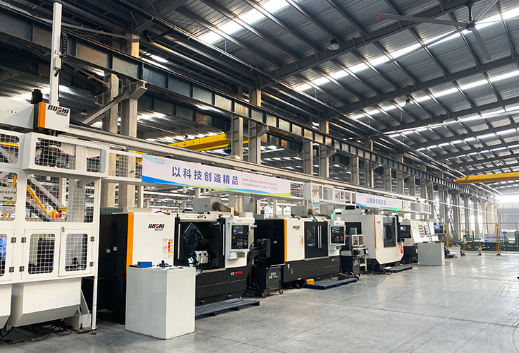
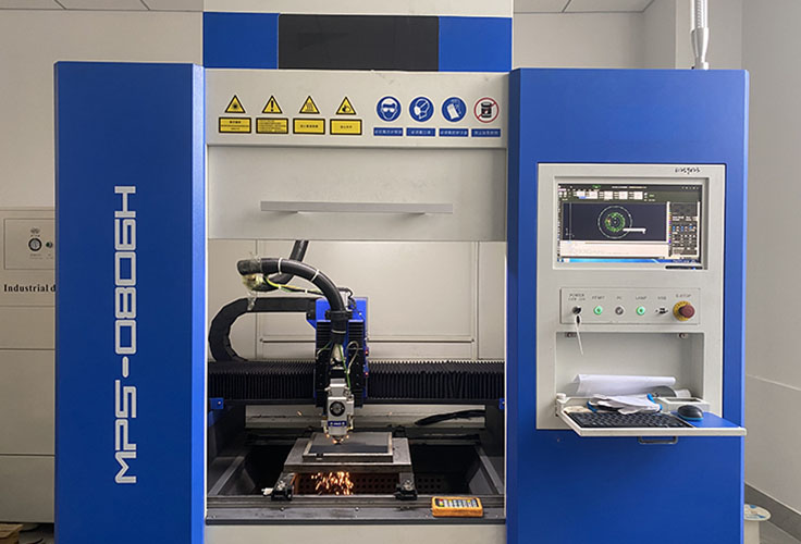
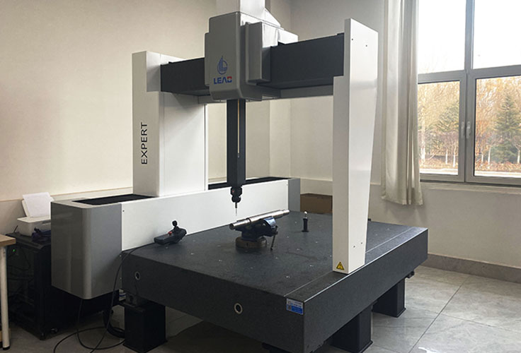
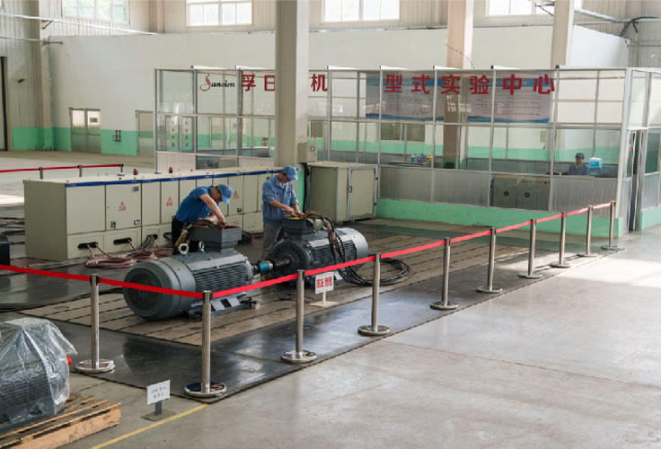
Our Type Test Center enables us to verify motor electromagnetic parameters before shipment. This national-level testing center evaluates torque characteristics, efficiency curves, insulation resistance, thermal rise behavior, and no-load excitation metrics. By checking that every motor's magnetizing current falls within strict parameters, we verify that our products deliver the specified electrical performance on the job.
Optimizing Rotational Drives for Challenging Global Environments
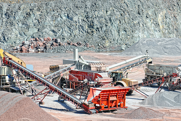
Heavy-duty high-torque motors built to handle dust, moisture, and variable mechanical loads without losing excitation efficiency.
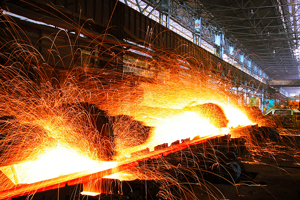
Thermally resilient designs engineered to maintain stable operational efficiency under high ambient temperatures and severe duty cycles.
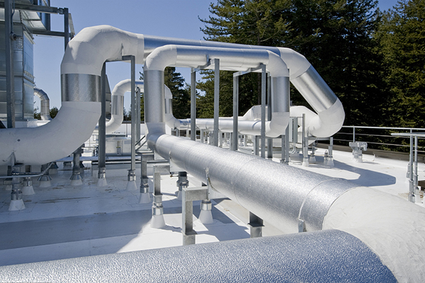
Continuous-duty fan motors optimized for long-term low-vibration operation, helping control building and tunnel ventilation energy costs.
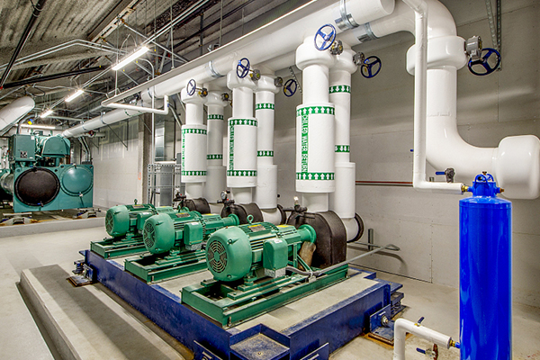
IP55/IP56 outdoor protection designs that maintain electrical integrity and efficiency in remote grid areas.
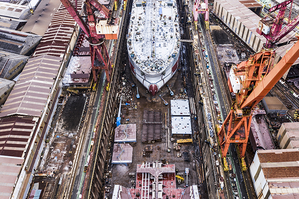
Marine duty motors certified by global registers (ABS, DNV, CCS) to withstand salt spray and demanding sea conditions.
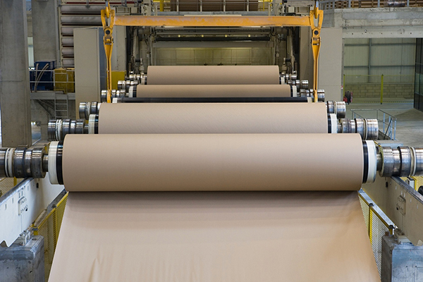
Corrosion-resistant housings paired with tight-tolerance windings, built to endure humid, chemical-laden pulp processing environments.
Next-Generation Magnetic Materials, Ultra-Low Resistance, and Smart Integration
The electric motor industry is undergoing a significant transition driven by global decarbonization initiatives and stricter minimum energy performance standards (MEPS), such as the European Ecodesign directives. As markets move from IE3 toward IE4 and IE5 ultra-premium efficiency classes, traditional motor architectures are reaching physical limits. The future roadmap of industrial rotating machines relies on advanced materials and magnetic path engineering.
To reduce losses, researchers are exploring amorphous alloy cores and nanocrystalline materials, which display significantly lower magnetic reluctance and hysteresis losses compared to traditional silicon steel. In addition, slot design and permanent magnet configurations, such as in Synchronous Reluctance Motors (SynRM), can drastically reduce magnetizing current losses by replacing rotor copper losses with pure magnetic reluctance torque.
At Sunvim, our R&D roadmap is centered on three main pillars:
Globally Verified for Safety, Reliability, and Industrial Grade Performance
Industrial motors must meet varying standards across different global markets. Shandong Sunvim Motor Co., Ltd. holds a comprehensive suite of international quality certifications, enabling our motors to integrate directly into projects worldwide.

ISO9001:2015
CE Certification

UKCA Conformity

UL Listing

SABS South Africa
CCS Marine

ABS Marine
DNV Classification
Clear Answers to Critical Engineering Questions About No-Load Current and Induction Performance
A high no-load current is typically caused by three main issues: structural air-gap deviations, core material degradation, or stator winding errors. If the mechanical air gap is too wide, the magnetic reluctance increases, requiring more magnetizing current to establish the flux. Similarly, degraded laminations or lower-grade silicon steel increase core losses. In some cases, a high no-load current can also indicate a winding mistake, such as fewer turns in the stator coils than specified.
As a rule of thumb, motors with more poles draw a higher proportion of no-load current relative to their rated current. For example, a 2-pole motor might have a no-load current that is 20% to 35% of its rated current. A 10-pole or 12-pole motor, however, may draw 50% to 65% of its rated current at no-load. This occurs because slow-speed, multi-pole designs require larger stator bores and have higher overall magnetic path reluctance, requiring a stronger magnetizing field.
Yes. While no-load current is primarily determined by stator winding turns and core lamination characteristics, mechanical issues like rotor eccentricity or damaged rotor bars can cause noticeable current fluctuations. Rotor eccentricity creates an asymmetrical air gap, causing the no-load current to fluctuate or read higher than normal. Winding testers and motor analyzers often use these variations to detect structural faults.
Variable Frequency Drives (VFDs) change both the voltage and frequency supplied to the motor, typically maintaining a constant Volts-per-Hertz ratio. At low speeds, VFDs often apply voltage boost to overcome stator resistance, which can increase the magnetizing current. In addition, VFD carrier frequencies introduce high-frequency harmonics that can increase core losses (hysteresis and eddy current losses) during no-load operation.
At no-load, the active current component (which covers friction and windage) is small, while the magnetizing current component remains relatively constant. Because this magnetizing current is purely reactive, the ratio of active to reactive power is low, resulting in a low power factor (often below 0.2). As load is added to the motor, the active component of the current increases to meet the mechanical demand, improving the power factor toward its rated value (typically 0.8 to 0.9).
Our Type Test Center evaluates no-load performance under controlled conditions. We run each motor at rated frequency and voltage until thermal equilibrium is reached, then measure current, voltage, input power, and speed. By separating the windage and friction losses from the core losses, we verify that the magnetizing current matches design models. This testing confirms that the motor will operate as specified when installed.
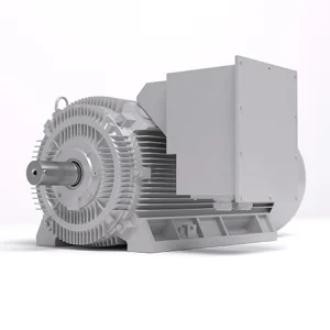
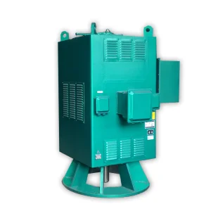
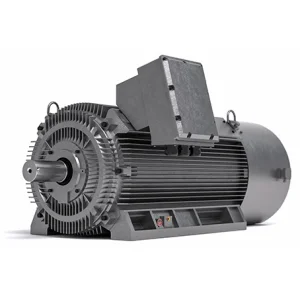
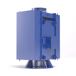
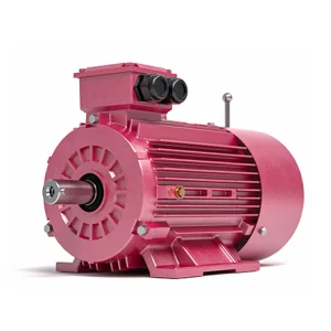
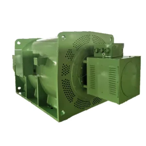
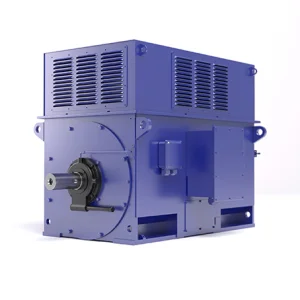
Select from our range of high-voltage induction and converter-fed systems.
 Sunvim Motor