Choosing a Reluctance Motor requires more than comparing rated power and purchase price. The motor must match the machine’s real operating conditions. A conveyor may need steady torque at low speed, while a pump often runs near one repeated duty point. A fast packaging axis may demand sharp acceleration, precise positioning, and frequent braking. These differences strongly influence motor size, controller selection, cooling, and expected service life.
Begin with the load profile, not the catalogue headline. Record starting torque, continuous torque, peak torque, speed range, cycle time, and overload duration. Then check the drive’s control method and available supply voltage. A motor can appear efficient on paper but perform poorly with an unsuitable inverter. Noise and torque ripple also deserve attention, especially near operators or sensitive equipment. Small details matter. Review manufacturer curves, thermal limits, bearing data, enclosure ratings, and tested efficiency values. Independent test reports can provide useful confirmation, although they may not represent your installation.
Experience shows that installation conditions often expose weak assumptions. Dust, heat, restricted airflow, and repeated starts can change the selection entirely. Ask whether maintenance staff can access the motor easily. Consider spare parts, commissioning support, and the supplier’s response time. A lower initial price may create higher lifetime costs through downtime or complicated controls. Still, no selection guide can remove every uncertainty. Real measurements may challenge the first calculation. Leave a sensible safety margin, but avoid oversizing without evidence. An oversized Reluctance Motor may reduce efficiency at light load and increase system cost. The best choice balances measured demand, control compatibility, environmental protection, reliability, and long-term operating value.
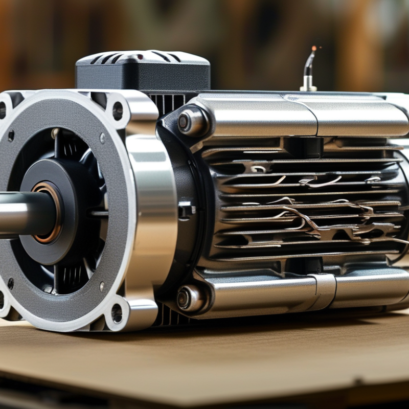
Choosing a reluctance motor starts with defining the operating requirements, not selecting a catalog rating. Record speed, torque, acceleration, duty cycle, braking events, and ambient temperature. A conveyor may need steady torque, while a pump may demand frequent speed changes. These profiles create very different thermal stresses.
The International Energy Agency reports that electric motor systems consume about 53% of global electricity. Industrial motor systems represent roughly 70% of industrial electricity use, according to its motor-driven systems analysis. Small efficiency gains therefore matter. Set measurable goals, such as peak efficiency above 92%, controlled acoustic noise, or a specific torque response. Check continuous and short-term overload torque separately. Also define the inverter’s voltage, switching limits, and sensor strategy before testing the motor.
Tips: Build a one-page load profile. Include five-minute speed and torque intervals. Measure the heaviest real load, not an ideal estimate. A neat spreadsheet can still lie. Validate assumptions with temperature rise, vibration, and sound measurements. Review the full efficiency map, rather than relying on one laboratory point. The U.S. Department of Energy’s Motor Systems Market Assessment also emphasizes system-level evaluation, because motor, drive, and load performance interact. Leave margin for dust, voltage variation, and aging. More margin is not always better; oversized motors can operate inefficiently.
Choosing a reluctance motor starts with its operating principle, not its rated power alone. A switched reluctance motor (SRM) creates torque when energized stator poles pull nearby rotor teeth into alignment. The rotor has no windings or permanent magnets. This design makes it mechanically robust and tolerant of high temperatures. However, phase switching can produce acoustic noise and torque ripple. In a workshop test, poor controller tuning made a small motor sound like a loose fan.
A synchronous reluctance motor (SynRM) uses a rotor with magnetic and nonmagnetic paths. The rotor follows the rotating stator field because magnetic reluctance differs across its axes. It normally needs an inverter for starting and speed control. Compared with an SRM, it often offers smoother torque and lower rotor losses. Its rotor geometry is more delicate, though. Manufacturing accuracy matters near the air gap. A fraction of a millimeter can affect efficiency.
Choose an SRM for rugged pumps, fans, or frequent thermal cycling when noise is manageable. Select a SynRM when efficiency and quieter operation matter more. Permanent-magnet-assisted reluctance motors add magnets to increase torque density. They can perform well, but magnets increase cost and temperature concerns. Test the motor with the real load, controller, and duty cycle instead of relying on catalogue curves. This step is often skipped. It should not be.
Choosing a reluctance motor starts with the load, not the catalog rating. Torque comes first. Record continuous torque, peak torque, acceleration time, and shaft inertia. A conveyor may need steady torque, while a pump may demand rapid speed changes. Compare the required torque with the motor’s torque-speed curve, including overload duration. A large peak rating is not useful if the drive cannot deliver the required current.
Speed changes everything. Check the operating range, base speed, overspeed limit, and braking method. Efficiency should be evaluated across the actual duty cycle, not at one attractive test point. Read efficiency ratings alongside their test conditions. Measure losses at low speed, high load, and frequent starts. These conditions increase heat in the windings, rotor, bearings, and power electronics. Allow room for ambient temperature, enclosure limits, and imperfect cooling. A small efficiency gain may disappear when control losses are ignored.
Control is not optional. Decide whether the application needs position feedback, sensorless operation, rapid reversal, or quiet torque production. Current ripple can create audible noise and vibration, especially at low speed. Verify the controller’s current range, switching capability, protection functions, and tuning flexibility. Use logged data from a prototype when possible. Simulation helps, but it can miss installation effects. That limitation deserves attention. Choose the motor and drive as one system, then test the weakest operating point before approving the design.
A reluctance motor should be selected for its working environment, not only its rated power. Industrial motor systems consume about 53% of global electricity, according to the International Energy Agency. Small specification errors can therefore create large operating losses.
Start with temperature, dust, moisture, and vibration. A motor beside a furnace may need insulation rated for elevated ambient temperatures. A dusty grain-processing area requires suitable enclosure protection and sealed bearings. Check the required IP rating against IEC 60034 guidance. Do not assume a higher rating always improves performance. Extra sealing can restrict cooling and increase frame temperature.
Match the motor’s speed range to the load profile. Fans usually need steady torque, while conveyors may demand frequent starts and short overloads. Switched reluctance motors can tolerate demanding duty cycles, but their acoustic noise may matter in occupied spaces. Synchronous reluctance motors often suit efficient variable-speed operation, especially with an appropriate drive.
Measure the real duty cycle. A nameplate rating can mislead. Record starts per hour, acceleration time, load changes, and available ventilation. The U.S. Department of Energy reports that motor-driven equipment represents roughly 70% of industrial electricity use. Efficiency deserves attention, but control compatibility matters too.
I have seen designs focus on peak torque and overlook maintenance access. That was an expensive lesson. Leave room for inspection, cable routing, and bearing replacement. Recheck assumptions after installation. Field temperature, dust buildup, and vibration may differ from the original survey. A practical choice balances efficiency, protection, noise, serviceability, and total operating conditions.
How to Choose a Reluctance Motor for Your Application
Choosing a reluctance motor starts with compatibility, not advertised efficiency. Check the required speed, torque, duty cycle, voltage, and control method. A motor sized only for peak torque may overheat during continuous operation. Confirm the inverter supports the motor’s current profile and switching requirements. Mechanical details matter too. Compare shaft dimensions, mounting holes, rotor inertia, and available enclosure protection. A small mismatch can create vibration, noise, or installation delays.
Reliability depends on the working environment. Review temperature, humidity, dust, shock, and expected operating hours. Ask for test data, insulation ratings, thermal limits, and documented quality controls. Field engineers should inspect bearings, cooling paths, and cable connections during evaluation. In my experience, laboratory results can look excellent while a poorly ventilated cabinet reduces performance. That assumption deserves a second look. Request a trial under real load conditions when possible.
Tips: Calculate lifetime cost, not purchase price alone. Include the controller, installation, energy use, spare parts, inspections, and downtime. A lower-cost motor may need more frequent bearing checks or specialized service tools. Build a maintenance schedule around actual access conditions. Can technicians reach the motor safely? Are replacement components available locally? Keep vibration and temperature records after commissioning. Small trends often reveal trouble early. Perfect predictions are rare. Regular evidence is better.
| Evaluation Dimension | Verification Requirement | Synchronous Reluctance Motor | Switched Reluctance Motor | Application Decision Guidance |
|---|---|---|---|---|
| Drive and controller compatibility | Confirm whether the existing inverter supports the required control algorithm, feedback device, current rating, switching frequency, and protection functions. | Normally requires a variable-frequency drive with rotor-position or sensorless control designed for synchronous reluctance operation. | Requires a dedicated switched-reluctance converter, phase switching control, and rotor-position information. | If the installed drive cannot be programmed for the selected motor, include the cost and space for a compatible converter. |
| Supply voltage and electrical ratings | Match rated voltage, phase configuration, current, frequency, insulation system, and short-circuit protection with the available electrical supply. | Commonly supplied as a three-phase motor connected to an inverter; the motor should not normally be connected directly to a fixed-frequency supply. | Powered through a purpose-built converter that independently controls the motor phases. | Select the motor and converter as one electrical system rather than comparing motor nameplate voltage alone. |
| Required speed range | Define minimum speed, continuous speed, maximum speed, acceleration time, overspeed limit, and any frequent speed reversals. | Suitable for efficient variable-speed operation when the inverter maintains synchronism and stays within the motor’s field-weakening limits. | Can provide a wide speed range, but acoustic noise, torque ripple, converter limits, and thermal performance must be checked at high speed. | Use the manufacturer’s continuous torque-speed curve, not only the peak-speed value, for sizing. |
| Torque and starting duty | Calculate continuous torque, peak torque, breakaway torque, inertia, load profile, starts per hour, and permitted acceleration time. | Provides smooth continuous torque when correctly controlled; starting performance depends strongly on the inverter and control settings. | Can deliver high starting torque and tolerate demanding acceleration profiles when the converter is correctly sized. | Select at least 10–20% additional continuous torque capacity only when justified by the duty cycle, thermal data, and acceleration requirements. |
| Efficiency and energy use | Compare efficiency across the actual operating load and speed points, including motor, converter, cooling equipment, and standby losses. | Often offers high efficiency over a broad variable-speed range because the rotor has no rotor copper winding. | Can achieve high efficiency, but converter losses and control strategy have a significant effect on system efficiency. | Use annual energy consumption and operating hours for comparison instead of relying only on nominal motor efficiency. |
| Reliability and thermal stress | Review winding temperature limits, insulation class, cooling method, bearing limits, overload capability, and protection against locked-rotor conditions. | The rotor has no electrical winding, reducing rotor copper-loss-related heating; stator winding temperature remains a primary limit. | The simple rotor can be mechanically robust, while stator switching, vibration, and thermal cycling require careful design validation. | Require documented temperature-rise tests or verified thermal models for the complete motor and converter assembly. |
| Noise and vibration | Set permissible sound-pressure and vibration limits and identify nearby personnel, sensors, precision equipment, or noise-sensitive areas. | Generally capable of smooth operation, although electromagnetic torque ripple can occur if control and rotor design are not optimized. | More likely to produce audible electromagnetic noise and torque ripple because phases are switched sequentially. | Request measured sound and vibration data at the actual operating speed and load before approval. |
| Environmental compatibility | Check ambient temperature, altitude, humidity, dust, water exposure, corrosive chemicals, hazardous-area classification, and enclosure rating. | Available with industrial enclosure and cooling arrangements, but inverter cabinet conditions must also be considered. | Motor and converter may have different enclosure, cooling, and environmental limits. | Specify the complete installation rating, including motor, converter, cables, filters, cooling fans, and control cabinet. |
| Regenerative braking | Determine whether the load can return energy during deceleration and whether a braking resistor, regenerative unit, or energy storage system is required. | Regenerative operation is possible with a suitable bidirectional drive and correctly configured DC-link management. | Regeneration is possible with an appropriate converter, but the converter must be designed to manage returned energy. | Include braking hardware in the system cost and cabinet heat calculation. |
| Maintenance requirements | Assess bearing lubrication intervals, alignment, cooling-path cleaning, cable inspection, encoder checks, and drive-fault diagnostics. | No brushes or rotor slip rings; routine maintenance typically focuses on bearings, cooling, connections, and the inverter. | Also avoids brushes and slip rings; additional attention may be required for converter cooling, phase connections, and vibration. | Create a preventive-maintenance schedule based on operating hours, contamination level, temperature, and bearing type. |
| Capital cost | Compare motor, converter, feedback devices, filters, cables, cabinet, commissioning, and required mechanical modifications. | Motor cost can be competitive, but a compatible variable-frequency drive and commissioning expertise are normally required. | The dedicated converter and control development can increase initial system cost, especially for low-volume applications. | Use total installed cost rather than motor purchase price as the selection baseline. |
| Lifecycle cost | Estimate energy, planned maintenance, spare parts, downtime, training, software support, and expected service life. | May provide favorable lifecycle economics in pumps, fans, compressors, conveyors, and other variable-speed duties. | May be attractive where starting torque, ruggedness, or wide-speed operation offsets higher control-system complexity. | Calculate payback using measured load profiles and realistic electricity, maintenance, and downtime assumptions. |
| Serviceability and spare parts | Verify availability of bearings, encoders, cooling fans, control boards, converters, parameter files, and qualified service personnel. | Service is generally straightforward when the motor and drive parameters are documented and replacement components are available. | Converter-specific knowledge and spare power-electronic modules may be important for minimizing downtime. | Require a documented fault-recovery procedure and a minimum spare-parts list before procurement. |
| Mechanical integration | Check frame size, shaft diameter, shaft height, mounting arrangement, inertia, coupling alignment, and available installation space. | Can often use standard industrial mounting dimensions, but the selected motor’s torque, speed, and cooling envelope must be confirmed. | Mechanical dimensions may differ from an existing induction-motor replacement and should be checked with the converter and cooling system. | Approve the dimensional drawing, shaft-load limits, and coupling arrangement before ordering. |
| Recommended fit | Select only after confirming duty cycle, control compatibility, environmental conditions, acoustic limits, and lifecycle economics. | Strong candidate for efficient, controlled-speed industrial applications requiring smooth operation and low rotor electrical losses. | Strong candidate for applications requiring high starting torque, robust construction, broad speed capability, or operation in demanding duty cycles. | Choose the option with the lowest verified total cost and risk—not simply the lowest motor price. |
: Record speed, torque, acceleration, braking events, duty cycle, and ambient temperature. Build a one-page load profile. Use five-minute speed and torque intervals. Measure the heaviest real load, not an ideal estimate.
Set measurable goals for efficiency, acoustic noise, torque response, and overload capacity. A target above 92% efficiency may be useful. Check continuous torque separately from short-term overload torque. Peak torque alone is insufficient.
A switched reluctance motor uses energized stator poles to pull rotor teeth into alignment. Its rotor has no windings or permanent magnets. It is robust, but switching can create noise and torque ripple.A synchronous reluctance motor uses magnetic and nonmagnetic rotor paths. It often provides smoother torque and lower rotor losses. Its rotor geometry needs accurate manufacturing. A fraction of a millimeter matters.
Consider it for rugged pumps, fans, and applications with frequent thermal cycling. It can tolerate demanding duty cycles. However, noise may disturb workers in occupied spaces. Poor tuning can make a small motor sound like a loose fan.
Choose it when efficient variable-speed operation and quieter performance matter. It normally requires an inverter for starting and speed control. Test its rotor accuracy near the air gap. The design is efficient, but not careless-proof.
Check temperature, dust, moisture, vibration, and available ventilation. A motor near a furnace may need higher-temperature insulation. A dusty processing area may require sealed bearings and stronger enclosure protection.More sealing can restrict cooling. That may increase frame temperature. A higher protection rating is not automatically better.
Fans usually require steady torque. Conveyors may need frequent starts and short overloads. Record starts per hour, acceleration time, load changes, and braking frequency.Match the motor’s speed range to actual operating conditions. A nameplate rating can mislead. Real duty data matters more.
Test the motor with the real load, inverter, controller, and duty cycle. Measure temperature rise, vibration, sound, and the complete efficiency map. Check voltage limits, switching limits, and sensor behavior.Do not rely on one laboratory point. A neat spreadsheet can still lie.
Leave space for inspection, cable routing, and bearing replacement. Include margin for dust, voltage variation, and aging. Avoid excessive oversizing because it can reduce operating efficiency.Recheck conditions after installation. Field dust, temperature, and vibration may differ from the original survey. That gap deserves attention.
Choosing the right Reluctance Motor begins with clearly defining the application’s operating requirements and performance goals, including load profile, duty cycle, desired speed range, starting conditions, and available power supply. Different reluctance motor types use distinct operating principles, so comparing their torque characteristics, control methods, efficiency, noise, and response is essential. The selection should reflect whether the application prioritizes high starting torque, precise speed regulation, energy savings, or simple operation.
After identifying the motor type, match its rated torque, speed, power, efficiency, and control requirements to the actual workload. Environmental factors such as temperature, humidity, dust, vibration, and installation space must also be considered. Finally, verify electrical and mechanical compatibility, expected reliability, maintenance needs, service accessibility, and total ownership cost. A well-matched Reluctance Motor can provide dependable performance and efficient operation when its specifications are carefully aligned with the application’s practical demands.
Sunvim Motor